Node (circuits)
In electrical engineering, node, refers to any point on a circuit where two or more circuit elements meet. Without any further knowledge, it is easy to establish how to find a node by using Ohm's Law: V=IR. When looking at circuit schematics, ideal wires have a resistance of zero. Since it can be assumed that there is no change in the potential across any part of the wire, all of the wire in between any components in a circuit is considered part of the same node.[1]
Voltage = Current * Resistance
since voltage is a measure of potential difference, the voltage between any two parts of the same node is:
Vab= (Current) * 0
So at any two points on the same branch of the circuit, the change in potential difference is 0. Therefore, throughout the entire node the voltage is the same.

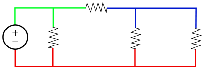
In this circuit diagram the voltage in the green node is the same throughout, likewise, the voltages in the blue node and the red node are the same throughout.
In most cases, the voltage difference between one point on a piece of metal (such as a copper wire), and the voltage at another point of the same piece of metal or on other bits of metal with metal-to-metal contact with the first piece of metal, is so small that it is usually considered insignificant. So every bit of that connected metal can be considered part of the same node.
Some notable exceptions, where the voltage difference is large enough to become significant, include:
- high-precision resistance measurements using a Kelvin connection
- the difference in voltage between ground and neutral, between the "neutral wire" and the "safety ground in a domestic AC power plugs and sockets, can be fatal. A properly installed electrical system connects them together at one (and only one) location, leading many people to the fatally incorrect conclusion that they are at "the same" voltage, or that the safety ground is "redundant and unnecessary".
- the Seebeck effect and the Peltier effect
- joints involving aluminium wire
Dots used to mark nodes on a circuit diagram are sometimes referred to as meatballs. [2]